The selfcontrolled chainreaction is nicknamed V1½ or V1.5 after the V1 and V2
weapons launched by Nazi-Germany during WWII, which were completely different beasts as is explained below
and can be seen in the
Discovery Channel documentary
https://www.youtube.com/watch?v=ro4ApX7EhJw Wings of the Luftwaffe (44m07s)
A very incomplete history of gas turbines is added.
Introduction
Heating a flammable liquid to its boiling point and using the
heat of the burning vapour to evaporate even more of the liquid
can obviously lead to a chainreaction.
We give the values for ethanol (85%).
In first appoximation Q(t)=Q(0) for t
≤
t0 and for t
≥
t0 dQ(t)/dt=Q(t)*
η
C/E
Where t0 is the moment the boiling sets in
(78.5 °C)
,
η
is the efficiency of heat transfer, C is the calorific value
(6000 cal/g)
and E the heat of evaporation
(approx. 260 cal/g)
.
So with only 9 % feedback we have an exponentially growing heat output
Q(t)
≈
Q(0)*exp(
η
tE/C) on a time scale of ½ second.
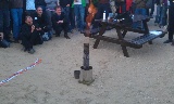
In other words a spectacular flame leaping from the chimney.
As with every exponential growth, non-linear effects restrict the chainreaction.
•
Very soon the internal flame get choked. Despite the chimney effect, not enough air can reach
the outpouring vapour and most of the action is outside the apparatus.
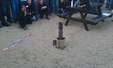
This is however a temporary effect and after a few seconds the next
blast will emerge.
•
It may take upto 5 minutes before the show starts, but in a couple of seconds
all fuel is consumed and the apparatus is left to cool down.
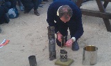
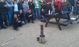
Safety precautions
Spectacular as a demonstration is, there have been half a dozen public demo's,
it is not dangerous provided a few safety precautions are taken into account.
•
Perform the demo outdoors on a free and flat stone platform.
•
Keep a safe distance once the preheater is ignited and the chimney is placed.
•
Never
look into the chimney, for instance when you think the apparatus is failing.
Wind may extinguish the preheater, but a windscreen can prevent that.
•
Do not use other fuel than 85% vacuum distilled ethanol (*).
This will burn safely and leave no residue.
•
Do not scale it up.
I use 60 ml ethanol and the same amount in the optional afterburner.
•
Soft solder can not be used in the construction.
I used stainless steel and hardsoldered brass.
Tin cans for the chimney can be reused.
•
The internal diameter of the C-shaped pipe should be large enough to prevent
pressure building up in the fueltank.
(*) Approximate values for other fuels:
fuel
C
E
C/E
unit
kcal/g
cal/g
dimensionless
ethanol(85%)
6
260
23
ethanol(100%)
7
200
35
kerosine
11
60
183
hydrogen(liquid)
34
110
309
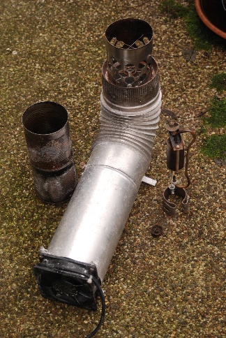
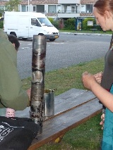
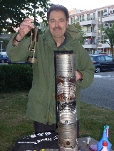
The demonstration
The design of the apparatus is modular. This allows easy variation
of aeration and chimney height.
An ethanol flame is barely visible in daylight. Applying a bit of grease
to the inside of the chimney solved that "problem".
Note the blue flame from the afterburner.
Using a fan
With an electric fan we can more or less prevent the choking effect.
The result is a hissing flame and a shorter burning time.
NAC 2011 festivities
To celebrate the 90th birthday of Prof. Kees de Jager
http://www.cdejager.com/
the chainreaction was, after a short explanation, demonstrated during
the 'Nederlandse Astronomen Conferentie 2011' on the island of Texel
on May 19 2011.
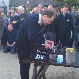
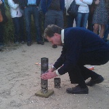
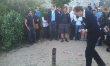
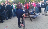
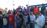
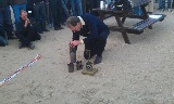
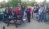
Birthday party
To celebrate the 65th birthday of Els Wegdam
LinkedIn
the chainreaction was, after a short explanation, demonstrated
in front of
Cultuurhuis Stefanus
in Utrecht on June 22 2014.
Click on
Start slideshow
. Every image will be shown for 6 seconds. Just click in the image to skip to the next image. Or view the individual images by clicking the thumbnails. Click in the large image to return to this page. You can also view the original images by clicking on
JPG
.
The V1
The V1 was a flying bomb powered by a pulse jet engine.
The fuel in flight was gasoline.
Click in the picture for the full resolution version (2096x1156).
As the construction of the pulse jet engine is simple and well known, a number
of people or groups have rebuild the engine for fun.
However the original design was intended to bomb London and other cities in Southeast England.
The lifetime of the inlet valves is limited to less than an hour (~100000 movements @ 45 Hz).
V1 on YouTube
There are numerous videos on YouTube about the V1, historical footage as well as post-WWII reconstructions.
•
Test runs of a rebuilt V1 pulse jet engine, note the details.
https://www.youtube.com/watch?v=Rdwbp6R2qM8 (3m50s)
- Opening music @ 0m13s
- Door opening at end of test @ 1m14s
- Vortex ring @ 1m57s
- Vague comments @ 2m34s
British engineers were succesful in building turbines, starting with marine
steam turbines developed by
Sir Charles Parson
for the
Turbinia
1894, top speed 34.5 knots (63.9 km/h),
and later for the
Mauretania
and its sistership the
Lusitania
.
Before and during WWII gas turbines were developed in the USA, Germany and the UK
which could be used for turbo-prop and jet-airplanes.
The most elegant design is the Rolls-Royce Derwent gas turbine
which powered the twin-engine Gloster-Meteor.
Click in the picture for the full resolution version (8512x4896).
A drawing of the thermodynamics of the Derwent from
A.J.C. De Lang & L.Suetens,
Toegepaste technische warmteleer. Click in the picture for the full resolution version (2476x1292).
•
A: 4 inlet ducts
•
B: impeller of compressor
•
C: 9 diffusor channels
•
D: 9 combustion chambers
•
E: turbine, 48 fixed and 54 moving blades
•
F: jet exhaust duct
•
G: connection shaft
•
H: cooling fan
More information
from G. Geoffrey Smith M.B.E.,
Gas Turbines and Jet Propulsion for Aircraft,
can be read
here
.
Sound
Hear the sound of the Derwent (wav).
WAV
mp3
You hear:
•
the clutch of the auxilary engine
•
rotating at low speed by the auxilary engine
•
first fuel injection
•
speed up to full power
•
the second half (17.6 s) is the reverse of the first half.
New records
On 7 November 1945, the official
air speed record by a jet aircraft was set by a Meteor F.3 at 975 km/h (606 miles
per hour). In 1946, this record was broken when a Meteor F.4
reached a speed of 991 km/h (616 mph). This record was again broken by
testpilot Roland Beaumont in 1946 with a speed of 1047 km/h.
In 1947 the Soviet Union bought (with approval of the British government!)
Derwent and Nene engines from Rolls-Royce. They were copied for the
MiG-15
(Mikoyan-Gurevich) jet fighter aircraft
(David Holloway,
Stalin and the Bomb
page 235).

 Heating a flammable liquid to its boiling point and using the
heat of the burning vapour to evaporate even more of the liquid
can obviously lead to a chainreaction.
We give the values for ethanol (85%).
Heating a flammable liquid to its boiling point and using the
heat of the burning vapour to evaporate even more of the liquid
can obviously lead to a chainreaction.
We give the values for ethanol (85%).


 Click in the picture for the full resolution version (8512x4896).
 Click in the picture for the full resolution version (2476x1292).